
Fast, Easy, Open Technique Development For NDT
BeamTool 11 is the world’s most popular application for designing ultrasonic inspection plans. Successful inspections start with a plan and BeamTool makes it easy to model, validate and document your Phased Array, TOFD and Conventional Ultrasonic inspection plans with confidence.

Focal Quality and Point Spread Function Simulation
Focal Quality and Point Spread Function simulation were introduced in BeamTool10 as a means of assessing the spatial sensitivity and resolution of FMC/TFM techniques. In BeamTool 11 these features have been improved and expanded to support Phased Array beamsets as well. The focal quality simulation allows the user to quickly visualize how the amplitude, shape and size of a point reflector (small side drilled hole) varies throughout the inspection region for a given technique. The user can use this information to select the appropriate essential technique parameters (aperture, focusing, index offset, etc.). Several focal quality metrics derived from the “Point Spread Function (PSF)” can be overlaid on the piece and their precise numerical values read at any given mouse position allowing for direct estimation of target resolution and sizing accuracy.


Technique Comparison
New in BeamTool 11 is the ability to quantitatively compare candidate inspection techniques (supported for FMC, Linear, Sectorial and Spread Beamsets). Beamsets generated with different probes (frequency, pitch, wedge parameters), apertures, focusing type (true depth, half path, unfocused) scan type (linear, sectorial, spread/compound) can be selected for comparison and appear in a split-screen view. Focal quality metrics associated with each technique are overlaid on the piece with a consistent palette to facilitate discriminating between them. The point spread function simulation and corresponding focal metrics (sensitivity, focal area, vertical resolution, horizontal resolution, lateral resolution, axial resolution) are displayed independently for each technique for ease of comparison.

Intelligent Alerts About Inspection Quality Issues (Warnings)
In BeamTool 11 the user is alerted to potential issues with the selected technique by a “Warnings” tab. Technique pitfalls to which the user will be alerted to in the “Warning” tab include:
- Using beams with low beam quality (eg. low transmitted amplitude)
- Specifying a focus which is beyond the effective nearfield for the array (focusing not possible)
- Setting a passive aperture larger than active aperture (affects near field approximations)
- Discrepancy between the wedge angle & piece surface angle (if they do not match)
- Beams intersect the weld at an angle that is outside of a configurable tolerance
- Attempting to use shear sound mode with a contact probe
- Beams do not enter the piece (eg. they intersect the damper or cannot be computed)
- Velocity mismatch between configured velocity and custom geometries
- Probe/Wedge parameters differ from the catalog values
- Weld contains cap but caps are ignored for relections
- Incorrectly configuring the instrument (eg. Number of available law channels)
- Cal block shape/piece parameters do not match
- Cal block is not large enough to fit auto-targets
- Custom geometry is improperly drawn (eg. self intersecting, zero length segments, etc…)
Warnings for all probes and beamsets can be viewed by selecting the Warnings dropdown in the toolbar and are displayed for the selected beamset under the Warnings heading.

Dynamic Workspace Information
A new “Workspace Information” option has been added in BeamTool 11 which when enabled, provides the user information about the beam nearest to the mouse position – this information includes travel path, time of flight, beam angle, etc.

NDT Axes
In response to popular demand, the option to change the coordinate system from the default global Cartesian coordinate system (x,y,z) to the NDT industry standard coordinate system (Index, Depth, Scan) is available in BeamTool 11. When the NDT axes are employed, all pertinent geometric information is labeled with respect to the Index, Depth, Scan axes which may facilitate reporting/technique documentation.

Expanded Support for Simulation/Visualizations in Custom Pieces
In BeamTool 11 the user can now use any of the Point Spread Function/Focal Metric simulation features in custom work pieces (previously only supported in standard pieces). The user may use the CAD tools to represent arbitrary inspection geometries and then select the appropriate component surfaces as the front and back walls of the piece.

Automatic Highlighting/Fading of Active/Inactive Beams & Probes
To facilitate workspace navigation, the probe/beamset closest to the user’s mouse position in the probe/beamset list is automatically highlighted.

Total Focusing Method, Full Matrix Capture and Overlay with real inspection data
“TFM (Total Focusing Methode)” und “FMC (Full Matrix Capture)” are new features in BeamTool 11.
The angle at the point of interest between the directions to the transmitting and receiving element of the array defines the numerical aperture NA = sin θ/2. The value of NA is responsible for the image quality with TFM. You may use the numerical aperture when creating the TFM frame (region of interest) in order to optimize the image quality.
“Overlay with real inspection data” is an additional new feature in BeamTool 11.
Certain real inspection data out of a Flaw Detector (Omniscan) may now be combined with the simulated beam set. For using this feature you need the „Olympus NDT data Access Library“, to be downloaded at: NDT Data Access Library 32bit.

Reflection and refraction on a part with cladding
Reflection and refraction on a part with cladding is a new feature in BeamTool 11.
The sound beams follow the laws of reflection and refraction with cladded parts.

Display of the beam intensity with sector scan and Import of a CAD drawing
For every shot (angle) the beam intensity will be evlauated and displayed in a bar diagram (bottom right). The angular scan range may now be optimized.
Intensities between 10% and 20% of the maximum intensity are displayed in orange, and red for <10%. For practical reasons angles with low intensities shall be avoided.
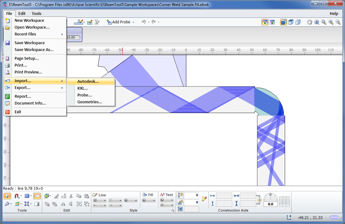
CAD drawings with splines can now be imported and processed.

Phased Array
BeamTool 11 was designed to meet the modern operator’s need for speed. Phased array technique development is more complex than that for conventional ultrasonic inspection and as such requires effective tools to help define the inspection approach.
BeamTool’s innovative approach to phased array enables linear, sectorial and an informative reference cursor option to be represented, helping to clearly convey weld coverage, HAZ coverage and probe position, in addition to critical dimensions. The beamset parameters dialog displays a visual representation of the transducer elements that are used to form the beamset.
Beam spread visualization allows you to more accurately see your beamset coverage for a specific dB drop, and near field visualization ensures that any focusing being performed is within the near field. True Depth, Projection and Half Path focus types can be visualized in your workspace and documented in your technique report.
Conventional UT
Conventional probes can also be modeled in BeamTool 11 with advanced support for beam spread and near field rendering.

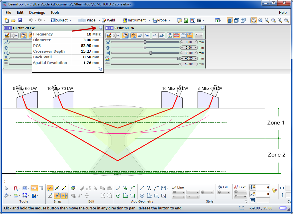
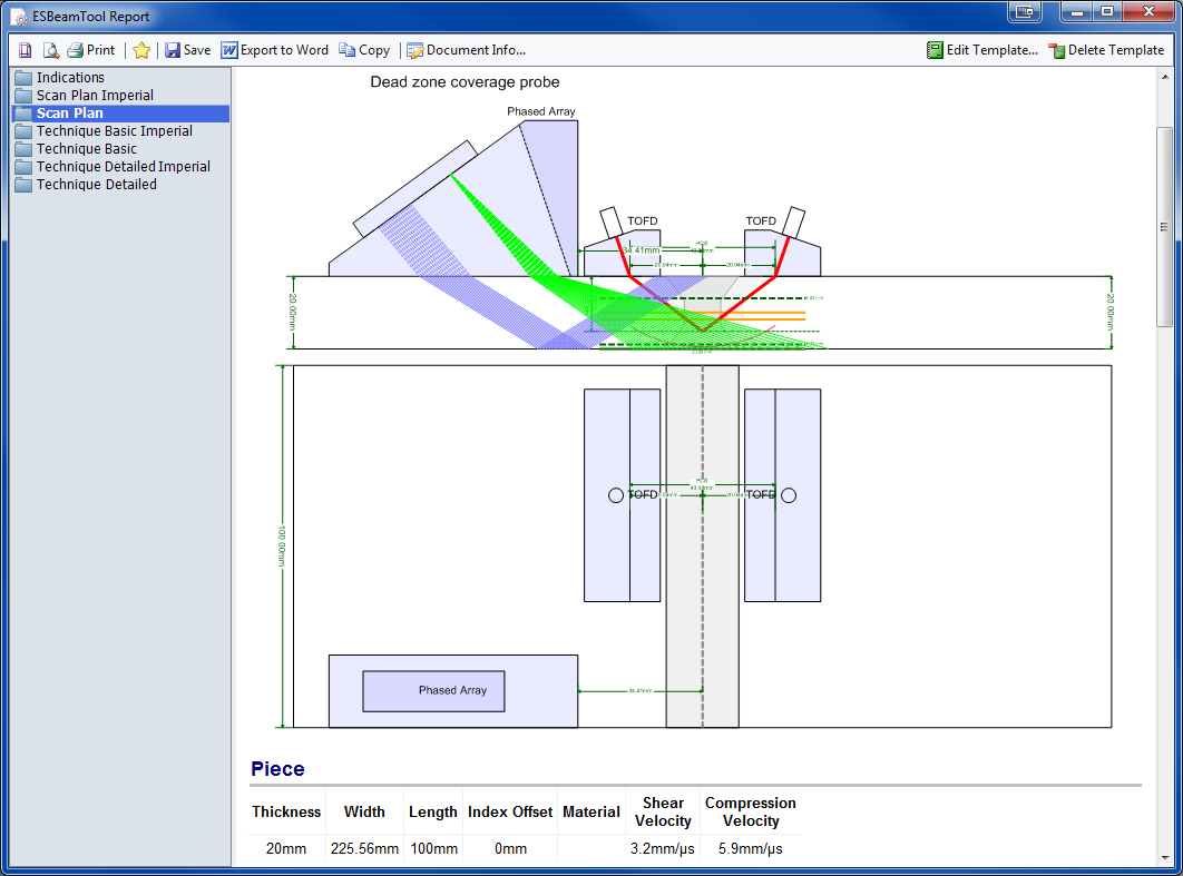
TOFD
Time-Of-Flight Diffraction support provides tools to visualize and confirm zonal coverage. TOFD techniques can be automatically annotated with cross-over dimensions and dead-zone depiction. Effortlessly define Probe Center Separation (PCS) by selecting the cross-over depth you want and BeamTool automatically positions the probes to target your requirements.
Multi-discipline Technique Development
Techniques can be created using multiple probes and multiple disciplines within a single workspace. Combine Phased Array with Conventional UT and TOFD probe configurations to ensure complete coverage. Pitch-catch is a useful technique for viewing unfavourable weld bevels or targeting geometry. Simply select P/C in the phased array configuration and the BeamTool 11 will solve and present the elements required; this feature can be set to reflect off the weld bevel face accounting for return refraction.
BeamTool 11 makes it easy to develop pitch-catch techniques for direct and indirect inspection using a single probe or a pair of probes.
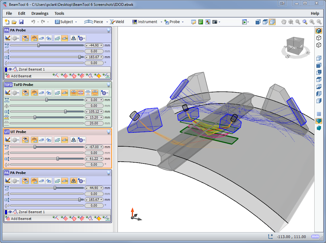
3D Workspace View
The 3D view will display your piece, annotations, probes and beams in an interactive viewing environment. Rotation, Panning and Zooming tools; Mesh, Solid and Surface modeling modes; and Perspective and Orthographic projection modes all provide a powerful, intuitive, highly interactive modeling tool for visualizing your techniques like never before. And along with the new “Construct Top View” tool, simple custom-drawn pieces can quickly be given depth and viewed in 3D as well.
CAD Functionality
BeamTool 11 integrates a powerful set of CAD tools that makes it easy to draw custom pieces to develop a scan plan for your inspection. Users can draw geometries of any shape and size and use the advanced ray tracing to accurately ensure and document proper coverage. The drawing tools have been greatly enhanced to make it even easier to draw and edit. Precision coordinate and size readout, along with the ability to snap and a Command Prompt for making complex specimen drawing precise, fast and easy. Multiple layers can be created to organize and filter your geometries.
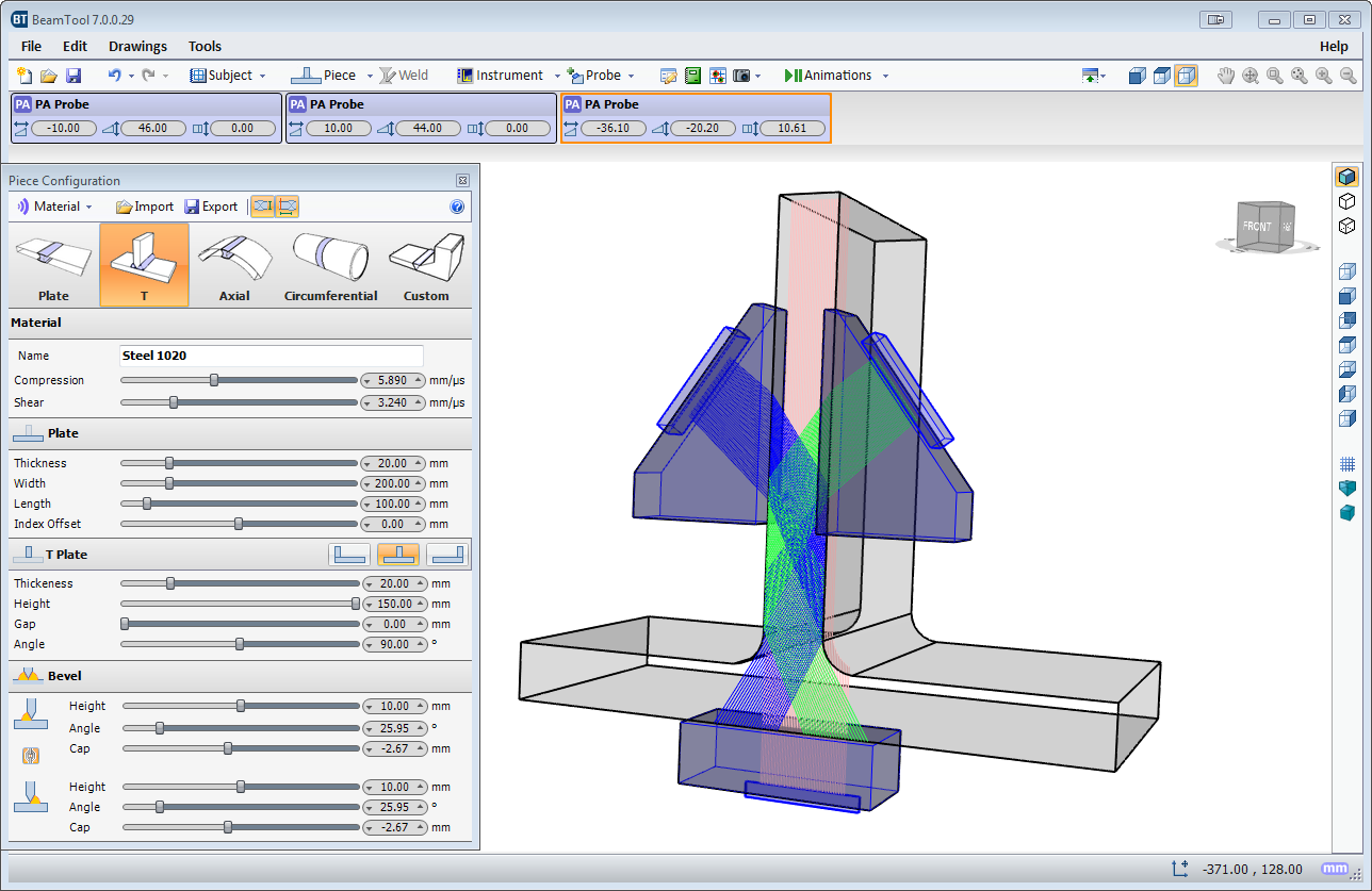
Piece Configuration
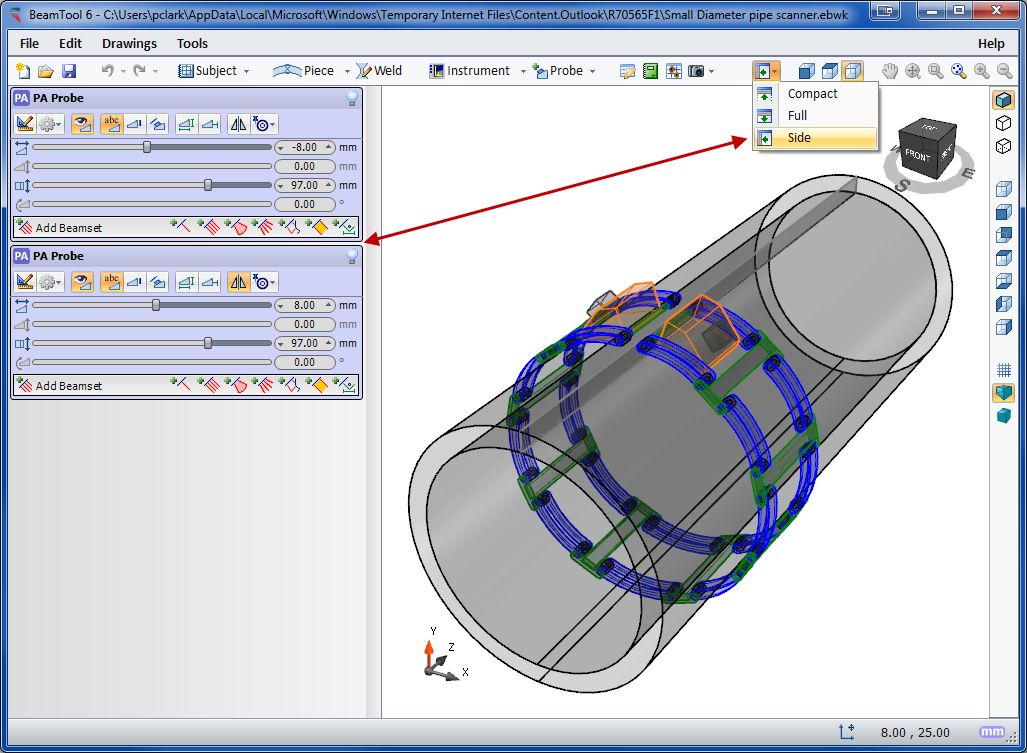
BeamTool 11 provides native support for ID/OD type pieces common in pipeline and boilers. The piece editor allows the piece to be easily defined using the OD and ID or thickness of a part. Once the part is configured, phased array and conventional probes can be pinned to the outside or inside of the part. As the user adjusts the probe location, the probe stays pinned to the part and revolves around it.
Weld Configuration
Pick from a list of standard weld configurations or use the advanced weld configuration editor to accurately create any weld profile you require. Weld cap geometries allow you to clearly illustrate how close you can get your probe to a weld while ensuring proper coverage.
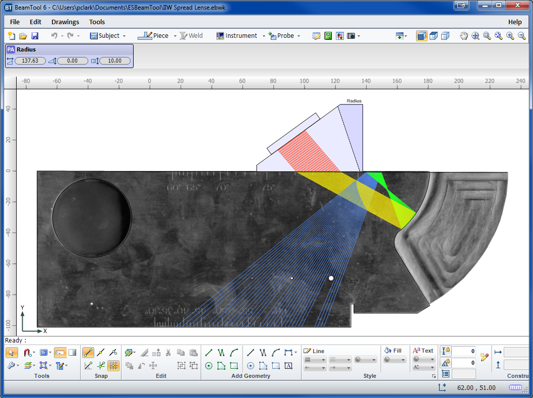
Bitmap Backdrops
Use the bitmap drawing tool to add images to your drawings. Bitmaps can be imported and scaled to be used as a backdrop or to use as a reference to trace over when drawing complex specimens.
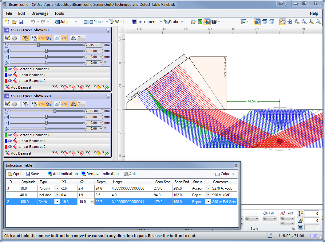
Defect/Indication Plotting
Defects/Indications can be entered into a table defining their spatial coordinates, then visualized on the workspace in 3D space. The amplitude of defects is visualized through a colored palettizer.
Configurable Reporting
HTML standards-based reporting allows reports to be generated and shared across the web or email. Report content can be copied into other programs, such as Microsoft Word, and edited for final presentation. Users can easily customize or create new reports containing the information they need. The built-in HTML editor allows reports to be constructed in an environment similar to a common word processor. Workspace fields can be dragged from a field picker into the template for inclusion in the report.
Requirements
- Operating system Windows 10 (x86, x64), Windows 11 (x86, x64)
- Microsoft .NET 8 Desktop Runtime 8.0.10 (x64) or higher
- Processor 1GHz or faster
- RAM 512 MB or more
- Hard disc 4.5 GB or more
Standard package
- BeamTool 11 as download (no shipment on data media) with SoftLock license
- No additional modules (Add-on). These must be ordered separately
- OnLine Help in Englisch (no printed operating manual)
Tips for the operation and use
- The SoftLock license uses a serial number to activate BeamTool on a single computer. If you want to use the license on another computer, you must first deactivate the software on the current computer before you can reactivate it on another.
- This option is best for users that do not need to run a single license on multiple machines and is most cost effective.
Possible influences on the results
- With the calculation of ray tracing BeamTool uses the geometrical data of the part, and its physical data (sound velocities) entered by the user, as well as all relevant data of the selected probe and delay line at room temperature (20°C). Further influences, e.g. the surface condition of the part and temperature deviations of the probe and delay may have an unexpected effect on the sound propagation. These influences, but also the material structure (sound attenuation, scattering and un-isotropy) of the real part are not considered in BeamTool! BeamTool only calculates the results based on the sound velocity entered by the user. Possible mode conversion, that may occur with sound reflection at boundaries are not taken into consideration, and may lead to unexpected artifacts with later practical application.The geometrical and technical data of the probes and delay lines or wedges filed in the integrated database relate to the data supplied to Eclipse Scientific by the individual probe manufacturers. Continuous development of new probes and wedges or changes by the manufacturer, even minor differences to the existing stored data, but also incorrect entries of values in the database, may have a negative influence on the calculation of sound propagation. However, with Ultrasonic inspection according to standards, probe and wedge data must always be checked using a designated reference block with artificial reflectors.BeamTool always calculates the acoustical axis of the corresponding beam based on the entered probe and wedge data. Any side or grating lobes of the sound beam are not considered.
- Summary: BeamTool calculates the sound propagation of the Ultrasonic wave based on a simple physical model, which best describes the physics of sound propagation and reflection. Influences, as described above, may effect the simulation results of BeamTool. Therefore it is very important to verify the results, when converting the BeamTool scan plan into practice!
Limitation of Eclipse Scientific’s Obligation & Liability
- The manufactur company Eclipse Scientific shall not be liable to Reseller or any of its customers for any special indirect, incidental or exemplary damages, including, but not limited to, loss of business, loss of profit, loss or damage resulting from the loss of data, inability to access Internet, or inability to transmit or receive information, caused by, or resulting from, delays, non-deliveries, or service interruptions caused by Eclipse Scientific or the Product, even if Eclipse Scientific has been advised of the possibility of such damages.
- Eclipse Scientific’s liability to Reseller and any customer of Reseller is limited to the purchase price received by Eclipse Scientific for the relevant Product.
*Our offer is solely meant for trade and industry, as well as for company owners. All prices are to be understood as strict net prices plus statutory VAT.