
Option “A-Scan SIMULATION” now worth €720.00 included in the price!
Fast, Easy, Open Technique Development For NDT
BeamTool 11 is the world’s most popular application for designing ultrasonic inspection plans. Successful inspections start with a plan and BeamTool makes it easy to model, validate and document your Phased Array, TOFD and Conventional Ultrasonic inspection plans with confidence.
Phased Array
BeamTool 11 was designed to meet the modern operator’s need for speed. Phased array technique development is more complex than that for conventional ultrasonic inspection and as such requires effective tools to help define the inspection approach.
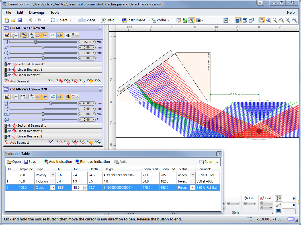
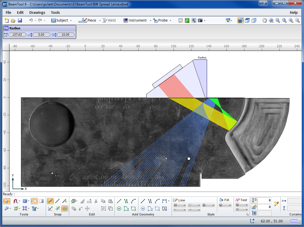
BeamTool’s innovative approach to phased array enables linear, sectorial and an informative reference cursor option to be represented, helping to clearly convey weld coverage, HAZ coverage and probe position, in addition to critical dimensions. The beamset parameters dialog displays a visual representation of the transducer elements that are used to form the beamset.
Beam spread visualization allows you to more accurately see your beamset coverage for a specific dB drop, and near field visualization ensures that any focusing being performed is within the near field. True Depth, Projection and Half Path focus types can be visualized in your workspace and documented in your technique report.
Conventional UT
Conventional probes can also be modeled in BeamTool 10 with advanced support for beam spread and near field rendering.

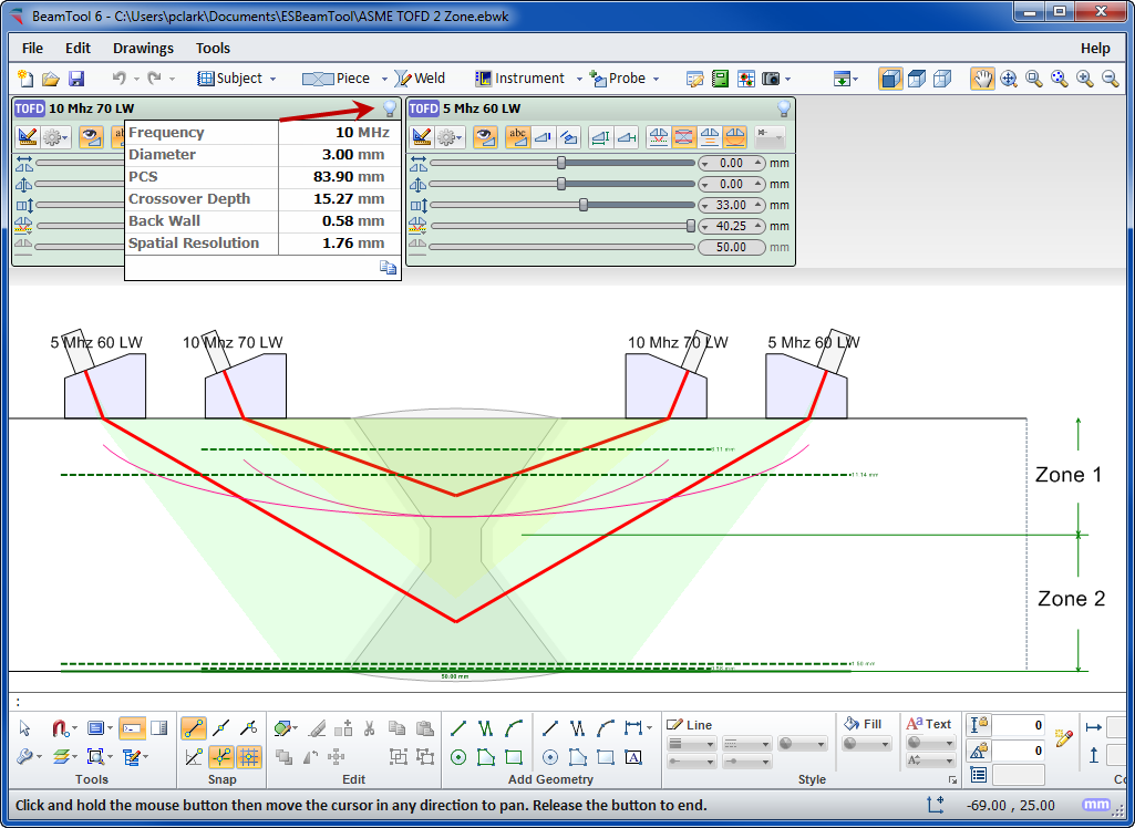
TOFD
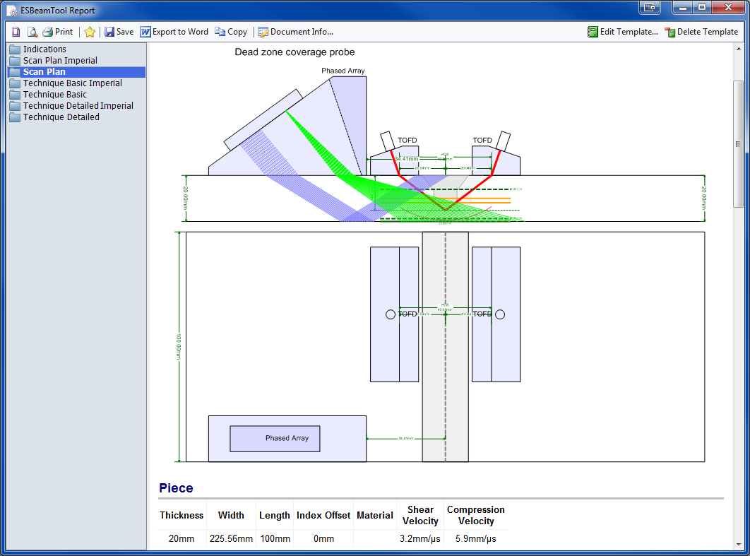
Time-Of-Flight Diffraction support provides tools to visualize and confirm zonal coverage. TOFD techniques can be automatically annotated with cross-over dimensions and dead-zone depiction. Effortlessly define Probe Center Separation (PCS) by selecting the cross-over depth you want and BeamTool automatically positions the probes to target your requirements.
Multi-discipline Technique Development
Techniques can be created using multiple probes and multiple disciplines within a single workspace. Combine Phased Array with Conventional UT and TOFD probe configurations to ensure complete coverage. Pitch-catch is a useful technique for viewing unfavourable weld bevels or targeting geometry. Simply select P/C in the phased array configuration and the BeamTool 10 will solve and present the elements required; this feature can be set to reflect off the weld bevel face accounting for return refraction.
BeamTool 10 makes it easy to develop pitch-catch techniques for direct and indirect inspection using a single probe or a pair of probes.
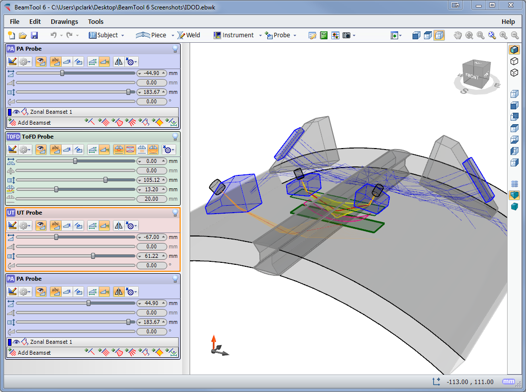
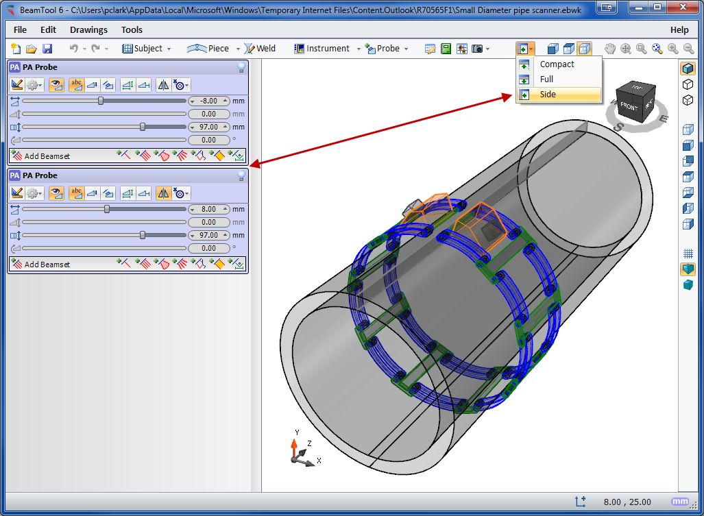
3D Workspace View
The 3D view will display your piece, annotations, probes and beams in an interactive viewing environment. Rotation, Panning and Zooming tools; Mesh, Solid and Surface modeling modes; and Perspective and Orthographic projection modes all provide a powerful, intuitive, highly interactive modeling tool for visualizing your techniques like never before. And along with the new “Construct Top View” tool, simple custom-drawn pieces can quickly be given depth and viewed in 3D as well.
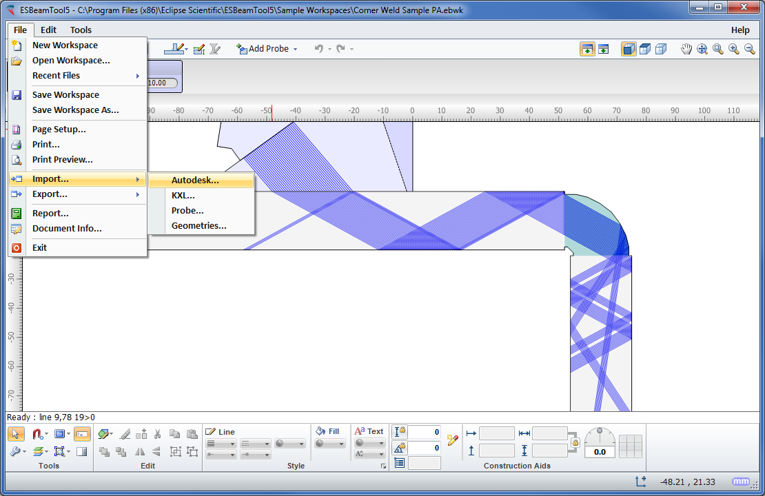
CAD Functionality
BeamTool 10 integrates a powerful set of CAD tools that makes it easy to draw custom pieces to develop a scan plan for your inspection. Users can draw geometries of any shape and size and use the advanced ray tracing to accurately ensure and document proper coverage. The drawing tools have been greatly enhanced to make it even easier to draw and edit. Precision coordinate and size readout, along with the ability to snap and a Command Prompt for making complex specimen drawing precise, fast and easy. Multiple layers can be created to organize and filter your geometries.
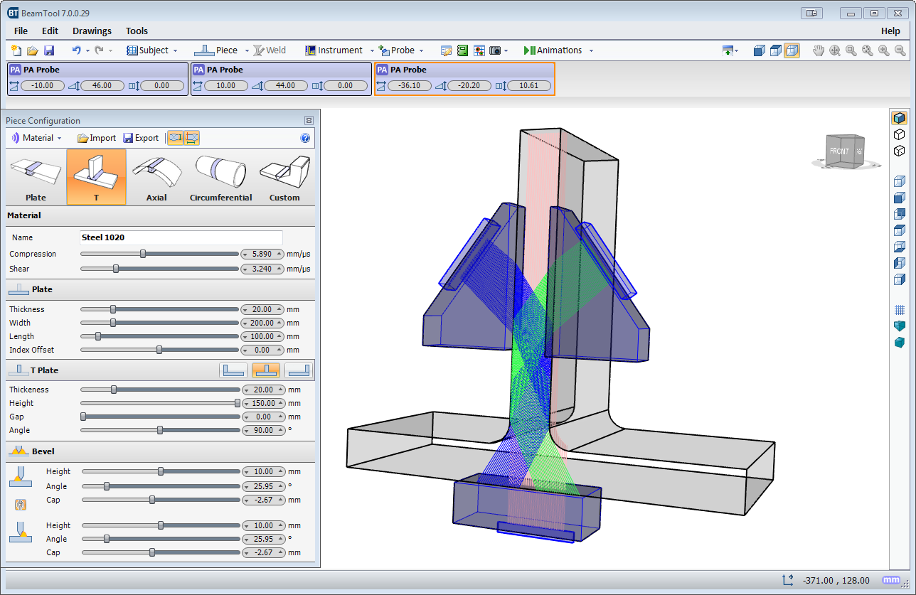
Piece Configuration
BeamTool 10 provides native support for ID/OD type pieces common in pipeline and boilers. The piece editor allows the piece to be easily defined using the OD and ID or thickness of a part. Once the part is configured, phased array and conventional probes can be pinned to the outside or inside of the part. As the user adjusts the probe location, the probe stays pinned to the part and revolves around it.
Weld Configuration
Pick from a list of standard weld configurations or use the advanced weld configuration editor to accurately create any weld profile you require. Weld cap geometries allow you to clearly illustrate how close you can get your probe to a weld while ensuring proper coverage.
Bitmap Backdrops
Use the bitmap drawing tool to add images to your drawings. Bitmaps can be imported and scaled to be used as a backdrop or to use as a reference to trace over when drawing complex specimens.
Defect/Indication Plotting
Defects/Indications can be entered into a table defining their spatial coordinates, then visualized on the workspace in 3D space. The amplitude of defects is visualized through a colored palettizer.
Configurable Reporting
HTML standards-based reporting allows reports to be generated and shared across the web or email. Report content can be copied into other programs, such as Microsoft Word, and edited for final presentation. Users can easily customize or create new reports containing the information they need. The built-in HTML editor allows reports to be constructed in an environment similar to a common word processor. Workspace fields can be dragged from a field picker into the template for inclusion in the report.
Requirements
- Operating system Windows 7 SP1 (x86, x64), Windows 8/8.1 (x86, x64), Windows 10 (x86, x64)
- Operating system Windows Windows Server 2008 SP2 (x86, x64), Windows Server 2008 R2 SP2 (x86, x64), Windows Server 2012 (x64), Windows Server 2012 R2x64)
- Microsoft .NET Framework 4.6 or higher
- Processor 1GHz or faster
- RAM 512 MB or more
- Hard disc 4.5 GB or more
Standard package
- BeamTool 10 as download (no shipment on data media) with HardLock license
- The HardLock license uses a HASP USB key to activate BeamTool. The HASP USB key ships within 10 days of purchase
- No additional modules (Add-on). These must be ordered separately
- OnLine Help in Englisch (no printed operating manual)
Tips for the operation and use
- The HardLock license uses a HASP USB key to activate BeamTool. BeamTool may be installed on multiple machines but will only run with the HASP key present.
- This option is best for users that need to run their BeamTool license on multiple machines.
Possible influences on the results
- With the calculation of ray tracing BeamTool 10 uses the geometrical data of the part, and its physical data (sound velocities) entered by the user, as well as all relevant data of the selected probe and delay line at room temperature (20°C). Further influences, e.g. the surface condition of the part and temperature deviations of the probe and delay may have an unexpected effect on the sound propagation. These influences, but also the material structure (sound attenuation, scattering and un-isotropy) of the real part are not considered in BeamTool 10!BeamTool9 only calculates the results based on the sound velocity entered by the user. Possible mode conversion, that may occur with sound reflection at boundaries are not taken into consideration, and may lead to unexpected artifacts with later practical application.The geometrical and technical data of the probes and delay lines or wedges filed in the integrated database relate to the data supplied to Eclipse Scientific by the individual probe manufacturers. Continuous development of new probes and wedges or changes by the manufacturer, even minor differences to the existing stored data, but also incorrect entries of values in the database, may have a negative influence on the calculation of sound propagation. However, with Ultrasonic inspection according to standards, probe and wedge data must always be checked using a designated reference block with artificial reflectors.
BeamTool 10 always calculates the acoustical axis of the corresponding beam based on the entered probe and wedge data. Any side or grating lobes of the sound beam are not considered.
- Summary: BeamTool 10 calculates the sound propagation of the Ultrasonic wave based on a simple physical model, which best describes the physics of sound propagation and reflection. Influences, as described above, may effect the simulation results of BeamTool 10. Therefore it is very important to verify the results, when converting the BeamTool scan plan into practice!
Limitation of Eclipse Scientific’s Obligation & Liability
- The manufactur company Eclipse Scientific shall not be liable to Reseller or any of its customers for any special indirect, incidental or exemplary damages, including, but not limited to, loss of business, loss of profit, loss or damage resulting from the loss of data, inability to access Internet, or inability to transmit or receive information, caused by, or resulting from, delays, non-deliveries, or service interruptions caused by Eclipse Scientific or the Product, even if Eclipse Scientific has been advised of the possibility of such damages.
- Eclipse Scientific’s liability to Reseller and any customer of Reseller is limited to the purchase price received by Eclipse Scientific for the relevant Product.
*Our offer is solely meant for trade and industry, as well as for company owners. All prices are to be understood as strict net prices plus statutory VAT.